


Explore additional upcoming features
See what we're working on, get an insight into what's going on below the
surface and which features you'll be able to take advantage of soon.
Wire Bonding Support
Wire Bonding Support enables the creation of components with defined 'Die Pads' that can be wired to regular pads or any copper on the main board using 'Bond Wires.' It allows for precise and efficient connections, enhancing the reliability and performance of your designs. Additionally, it offers comprehensive control over wire placement, loop height, and diameter, ensuring flexibility and precision in complex PCB layouts.

Unified Login
Unified Login allows signing in to an Altium Account through an external browser using various methods, including direct email credentials, linked Facebook or Google accounts, or Single Sign-On (SSO). This feature is a streamlined login mechanism integrated with Altium Designer for easy account access.
Harness and Multi-Board View Only Mode
Harness and Multi-board View Only Mode allows to explore previously inaccessible features with sample data provided during installation. The benefits include the ability to collaborate with colleagues on these projects, even if you can't modify them, and the option to generate outputs like PDFs of source documents and defined outputs from associated OutJobs.

Multi-Board Support for External Peripherals/Components
Multi-Board support for external peripherals/components involves the inclusion of external peripherals or components not part of regular child PCB board assemblies through custom parts or connections as new object types. With cable and harness connections, components placed in multi-board designs can interact, offering a comprehensive system diagram within the multi-board schematic document.

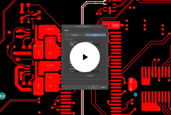
Static Phase Matching
Static Phase Matching enables the static alignment of differential pair lengths as part of the automatic differential pair length tuning process. This feature is crucial for maintaining the integrity of high-speed signal transmissions across PCB layouts.

3D Mechatronic Integrated Device Design
The 3D layout tool for Mechatronic Integrated Device (MID) designs seamlessly merges electronic and mechanical elements, opening up possibilities in diverse fields like wearables, medical devices, and automotive components. The tool simplifies the 3D design process with easy integration, synchronized design, logic-driven layout, and precise placement. It also ensures production-ready data export. The tool is user-friendly, eliminating the need for complex workarounds and making it suitable for the entire 3D-MID design process.

Dynamic Phase Matching for Differential Pairs
Dynamic phase matching for differential pairs with autotuning controls both static phase mismatches and dynamic phase discrepancies that can occur during bends or fan-outs in the routing process. By considering the electrical types of pads at each end of a routed differential pair, and applying tuning based on the source/load specification, it ensures precise tuning of differential pairs.

QR Code Support
The QR Code functionality allows you to control the full width of the code, its horizontal and vertical margins, and whether it appears inverted, all through the Properties panel. This addition enhances the usability and interactivity of your PCB designs.

Routing Neck-Down Rule
The Routing Neck-Down Rule provides detailed control over the width and length of narrow traces in high-density areas of a PCB layout. This feature allows to define maximum allowable lengths for traces that are narrower than standard widths, which are essential in compact PCB designs.


Selection Box for Component 'Push'
The Selection Box for Component 'Push' enhances user control by observing user-defined geometries for the component selection bounding box during component movement in 'Push obstacles' mode. This helps to precisely manage component placement within specified boundaries, optimizing layout flexibility and accuracy.

Simulation S-parameters Analysis
The Simulation S-parameters (scattering parameters) tool facilitates an approach for describing networks based on the ratio of incident and reflected microwaves. These ratios can be subsequently used to calculate the properties of a circuit including input impedance, frequency response and isolation. While this type of analysis is primarily for RF circuits and components, it is equally useful for any circuit with at least two sources (ports). Using S-parameter data as a tool to optimize your design can lead to cost savings, improved product quality, and a competitive edge in the marketplace.

ODB++ v.8.1 support
Altium Designer's enhanced ODB++ data generation allows users to choose between the latest v.8.1 and legacy v.7.0 formats within a single installation.
Support for v.8.1 brings a range of highly desirable features and functionality, including Variants support. This allows for the generation of data for all defined variants either collectively in a single instance or separately. It also facilitates Flex/Rigid-Flex manufacturing through the addition of various layer sub-types and implements zones file support, making it easy to distinguish rigid and flex regions of the board.
These improvements ensure a versatile and efficient ODB++ data generation experience, addressing diverse design and manufacturing requirements.
Auto-Shrinking During Interactive Routing
Auto-shrinking during Interactive Routing allows to effortlessly narrow traces to the applicable width in tight spaces as they route, thereby enhancing routing flexibility.

''Obey Rules' Option for Polygon Pour Properties
The 'Obey Rules' option for Polygon Pour Properties streamlines the removal of narrow necks within solid polygon pours, saving valuable design time. It ensures adherence to design constraints by automatically managing necks narrower than a specified width, simplifying the process of rule compliance.

Simulation Stress Analysis
The Stress Analysis simulation tool computes critical operating conditions like maximum voltages, currents, and power dissipation for components. It examines these conditions against predefined limits specified in a component's stress model, allowing for early identification of potential points of failure. This precision supports the selection of robust components, enhances design efficiency, and minimizes the risk of costly failures, contributing to improved overall design quality and reliability.

You Deserve the Best in PCB Design
Design more efficiently and bring your projects to life faster than ever before.
As a PCB designer, your tools can either empower or limit your work. Unleash your full potential with Altium Designer®, the world’s most popular PCB design software, and Altium 365, our cloud-based platform that helps you work from anywhere and connect with anyone.